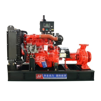
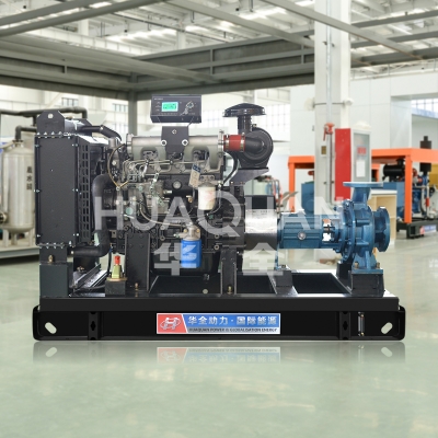
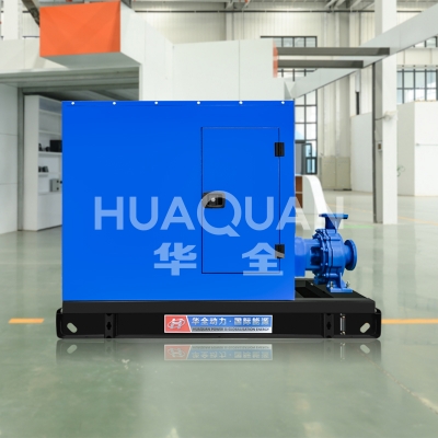
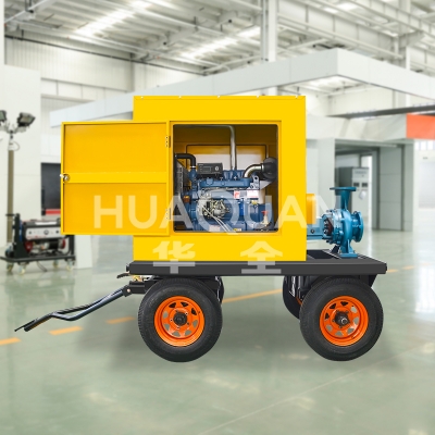
A
centrifugal water pump is a mechanical device that transports liquids through the centrifugal force generated by the rotation of an impeller. It is currently the most widely used and produced pump type in the world, enjoying great popularity due to its relatively simple structure, wide flow range, uniform flow rate, and easy maintenance.
I. Core Working Principle
The working principle of a centrifugal pump is based on the conversion of centrifugal force and kinetic energy into pressure energy.
Priming: Before starting, the pump casing and suction line must be filled with the liquid to be transported (called "priming"). This is crucial for the pump to properly suction water (unless it is a self-priming centrifugal pump).
Impeller Rotation: The electric motor drives the pump shaft, causing the impeller to rotate at high speed.
Centrifugal Force: The liquid, under the influence of the impeller's blades, rotates at high speed. The strong centrifugal force generated by the rotation propels the liquid from the center of the impeller (inlet) along the channels between the blades to the outer edge of the impeller (outlet).
Kinetic Energy Increase: The liquid acquires a higher velocity under the influence of centrifugal force, thereby increasing its kinetic energy. Conversion of Pressure Energy: High-speed liquid flows from the impeller into the pump casing (or guide vanes). The flow path of the pump casing is designed to gradually expand (diffuser principle), gradually reducing the flow velocity of the liquid. According to the law of conservation of energy (Bernoulli's equation), the reduced flow velocity results in a decrease in kinetic energy, which is largely converted into the liquid's pressure energy (head/lift).
Discharging Liquid: The pressurized liquid is discharged from the pump outlet and transported into the pressure pipeline to its destination.
Creating a Vacuum or Low-Pressure Area: When liquid is thrown toward the outer edge of the impeller, a localized vacuum or low-pressure area is created at the center of the impeller inlet.
Continuous Intake: Due to the pressure difference between the liquid surface pressure in the suction pipeline (usually atmospheric pressure or vessel pressure) and the low-pressure area at the impeller inlet, new liquid is continuously forced (drawn) into the center of the impeller to replenish the liquid being ejected, thus achieving continuous liquid delivery. In simple terms: High-speed rotating impeller → centrifugal force throws liquid → liquid gains high-speed kinetic energy → pump casing expands pressure → kinetic energy converts to pressure energy → high pressure discharge → low pressure at the center of the impeller → new liquid is drawn in. The cycle repeats.
II. Main Components
Impeller:
The core component directly applies pressure to the liquid. It typically consists of a front cover, a rear cover, blades, and a hub.
Types:
Based on suction method: Single-suction impeller (liquid enters from one side), Double-suction impeller (liquid enters from both sides, balancing axial forces and resulting in high flow rate).
Based on structure: Closed impeller (with front and rear covers, high efficiency, most common), Open impeller (without front and rear covers or only a rear cover, suitable for liquids containing impurities), Semi-open impeller (with only a rear cover).
Based on blade shape: Backward-curved blades (most commonly used, high efficiency, stable head-flow characteristic curve), Radial blades, Forward-curved blades (high head but lower efficiency, prone to overload).
Pump casing:
Houses the impeller and collects, guides, and converts the high-speed liquid thrown out by the impeller into pressure energy. Types: Volute (spiral diffuser, simple structure, high efficiency), Guide vane (fixed guide vanes installed on the outer periphery of the impeller, commonly used in multi-stage pumps).
Pump shaft:
Transmits power and supports the rotation of the impeller. It must possess sufficient strength and rigidity and is typically made of stainless steel or carbon steel.
Shaft seal:
A critical component! It prevents high-pressure liquid within the pump from leaking to the outside through the gap between the pump shaft and the pump casing, or prevents air from entering the pump (in the case of negative pressure on the suction side).
Common types:
Packing seal: Simple structure and low cost, but requires regular maintenance (such as tightening or replacing the packing) and allows a small amount of leakage for lubrication and cooling.
Mechanical seal: Provides excellent sealing performance, minimal (even zero) leakage, and long maintenance intervals, making it the most widely used. It consists of a dynamic ring, a static ring, and a spring.
Dynamic seals (such as the expeller seal): Commonly used in slurry pumps that transport solid particles.
Bearings: Support the pump shaft, bear radial and axial loads, and ensure smooth shaft rotation. Rolling or sliding bearings are typically used.
Seal Ring/Gland Ring:
Installed between the outer edge of the impeller inlet and the pump casing (or between the impeller cover and the pump casing). This creates a small gap, reducing backflow and leakage from high-pressure areas to low-pressure areas, thereby improving pump efficiency. It can be replaced when worn.
Coupling:
Connects the pump shaft and motor shaft, transmitting torque (power). Flexible couplings are often used to compensate for installation errors and absorb minor vibrations.
Base/Bracket:
Supports and secures the pump body and motor.
III. Main Features and Advantages
Wide Flow Range: Covers low to very high flow rates (from a few liters/minute to tens of thousands of cubic meters/hour).
Stable Flow: Output flow is continuous and smooth, with minimal pulsation.
The relatively simple and compact structure makes it easy to manufacture, install, and maintain.
Versatile: Capable of pumping a variety of liquids, including clean water, chemical solutions, and oils (material compatibility must be considered). Adjusting the speed, impeller diameter, or number of stages allows for flexible adaptation to different operating conditions. Easy Adjustment: Flow rate can be easily adjusted via the outlet valve (note: valve adjustment results in energy loss).
High Speed: Can be directly connected to high-speed motors or steam turbines, and is relatively lightweight.
No Self-Priming Capability (Standard): The pump must be primed or maintained at positive suction pressure before startup. However, self-priming centrifugal pumps are specially designed variants that can automatically vent and prime.
IV. Key Performance Parameters
Flow Rate (Q): The volume or weight of liquid delivered by a pump per unit time. Common units include cubic meters per hour (m³/h), liters per second (L/s), and gallons per minute (GPM).
Head (H): The effective energy gain per unit weight of liquid passing through the pump (equivalent to the pressure height the pump can provide). Common units include meters (m), feet (ft), megapascals (MPa), bar (bar), and pounds-force per square inch (psi). Note: Head does not equal height difference! It includes the total energy required to overcome factors such as lift height, pipe resistance losses, and outlet pressure requirements.
Speed (N): The frequency of rotation of the pump shaft. Unit: revolutions per minute (rpm).
Power:
Shaft power (P_s): The energy transferred to the pump shaft by the prime mover (motor).
Effective power (P_e): The power actually transferred to the liquid by the pump. P_e = ρgQH (where ρ represents the density of the liquid and g represents the acceleration due to gravity).
Efficiency (η) is the ratio of effective power to shaft power. It evaluates the effectiveness of the pump's energy conversion. η = (P_e / P_s) * 100%.
Net Positive Suction Head Required (NPSHr) is the minimum suction head required by the pump to prevent cavitation. It is typically expressed as absolute pressure minus the saturated vapor pressure of the liquid. This is a characteristic parameter of the pump. Cavitation is a major threat to centrifugal pump operation!
Net Positive Suction Head Effective (NPSHa): The effective suction head actually provided to the pump inlet by the system (also expressed as absolute pressure minus the saturated vapor pressure). This parameter is determined by the installation system. Performance curve: A graph depicting the relationship between pump head (H), shaft power (P_s), efficiency (η), and flow rate (Q) under constant speed conditions. This is an important reference for pump selection and operation.
V. Main Application Areas
Centrifugal pumps are extremely widely used, covering nearly all industrial and civil applications requiring liquid transport:
Building water supply and drainage: domestic water supply, fire water supply, building drainage, and air conditioning water circulation.
Municipal engineering: water intake, pressurization, and transportation at waterworks; lifting, return flow, and chemical dosing at sewage treatment plants.
Industrial processes:
Chemical, petroleum, and petrochemical: transportation of raw materials, products, solvents, and coolants.
Power: boiler feed water, condensate, and cooling water circulation.
Pharmaceutical: process water and liquid chemical transportation.
Food and beverage: bottling of raw materials, water, and finished products.
Mining and metallurgy: slurry transportation, cooling water, and process water.
Agricultural irrigation: pumping for irrigation.
HVAC: chilled water and cooling water circulation. Ships: Bilge pumps, ballast water pumps, fire pumps, cooling water pumps, etc.
VI. Selection Considerations
Clarify the pumping medium: liquid properties (clean water, sewage, oil, acid/alkali solution, slurry?), temperature, viscosity, corrosiveness, presence of solid particles, and particle size/hardness. Determine the pump material (cast iron, stainless steel, plastic, or specialty alloy) and construction (open impeller or closed impeller? Seal type).
Determine flow requirements: What are the maximum, normal, and minimum flow rates required? Is there a range of flow?
Calculate the required head: This is crucial! The total system head must be accurately calculated, including:
Actual geometric lift (suction head + discharge head).
All longitudinal resistance losses (friction losses) and local resistance losses (e.g., valves, elbows, reducers, etc.) in the suction and discharge piping.
Required end pressure on the discharge side (e.g., nozzle pressure, tank pressure).
A safety margin is typically set at 5% to 10% of the calculated value. Confirm system NPSHa: Calculate the effective net positive suction head (NPSHa) of the device. The required net positive suction head (NPSHr) of the selected pump must be less than (NPSHa minus the safety margin, typically 0.5-1m). Otherwise, cavitation will occur and damage the pump.
Select pump type and number of stages:
Based on the flow rate and head, and in conjunction with performance curves, preliminarily determine the pump type (single-stage, multi-stage; single-suction, double-suction; horizontal, vertical).
Single-stage pumps have a simple structure and relatively low lift height.
Multi-stage pumps: Multiple impellers are connected in series to achieve high head.
Double-suction pumps: High flow rates and well-balanced axial forces.
Determine speed and drive type: Direct motor drive is typically used. Determine the appropriate motor power (must be greater than the pump's shaft power, and consider starting and overload requirements).
Consider the environment and installation: installation space, indoor/outdoor use, explosion-proof requirements, noise requirements, etc.
Focus on efficiency and cost: Select an energy-efficient model based on the requirements, while also considering the overall lifecycle cost, including initial investment and operating and maintenance costs. Consult the Supplier/Engineer: For complex operating conditions or special media, it is recommended to consult a professional pump supplier or engineer for accurate model selection.
VII. Key Operation and Maintenance Considerations
Before Starting:
Check connections, lubrication, and cranking (for smooth rotation).
Ensure the pump casing and suction line are fully filled with liquid! (Non-self-priming pumps)
Close the outlet valve before starting (to reduce starting current).
During Operation:
Monitor current, pressure, flow, temperature, vibration, and noise.
Check for shaft seal leakage (mechanical seals allow for trace leakage, while packing seals allow for small droplets).
Avoid operating with the outlet valve closed or at very low flow rates for extended periods (this can lead to overheating).
Shutdown:
First, close the outlet valve (to prevent backflow and impact).
Then disconnect the power supply.
Regular Maintenance:
Regularly replace the lubricating oil or grease according to the instructions in the manual.
Check the alignment of fasteners and couplings.
Regularly inspect and replace wearing parts (seals, shaft seals, bearings, etc.).
Drain the pump if it is not in use for an extended period of time and take rust-proof measures.
Summary
Centrifugal pumps, with their high efficiency, reliability, and versatility, have become a mainstream equipment for liquid transportation. Understanding their operating principles, structure, and performance parameters is fundamental to proper selection, installation, operation, and maintenance. In particular, accurately calculating the required head and ensuring sufficient Net Positive Suction Head (NPSHa) during selection are crucial for avoiding operational problems and ensuring long-term reliable pump operation.
We hope this detailed introduction provides a comprehensive understanding of centrifugal water pumps! For more information, visit:
http://www.huaquan168.com/


